My Build of "Tom's Easy CNC Mill" - Part II

November 2009


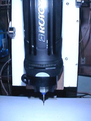
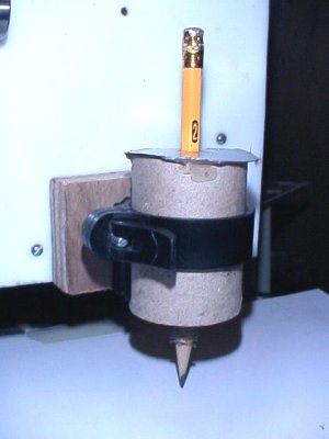
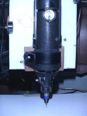
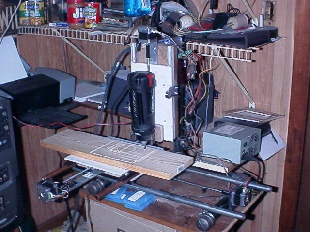
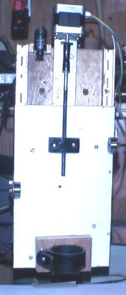
This was my first Z-stage build. To the left of the motor is a limit switch. The lower mount came with my Rotozip.

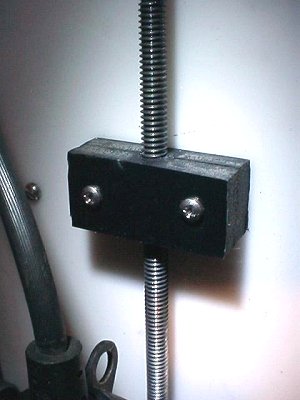
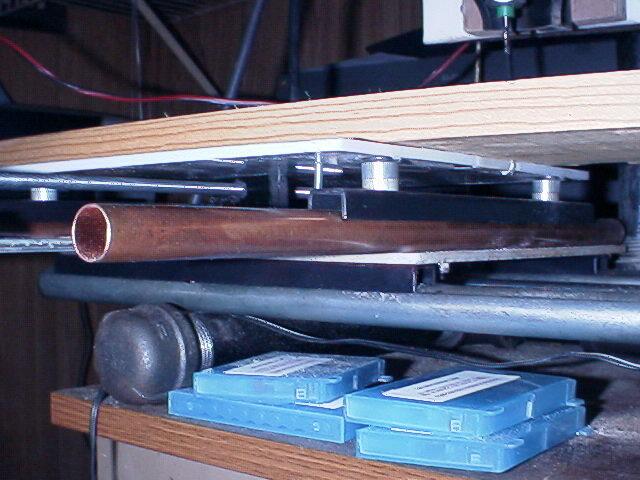
I didn't try to use marble bearings in a vertical channel because it just sounded like trouble. Instead, I used steel conduit sliding in the steel channel. Since it was hanging vertically, friction was mainly a function of the tightness of the two roller bearings holding the table.

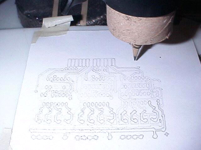
Unfortunately, it turned out that routing the copper off of circuit boards created enough sideways pressure that, unless the table was held very firmly, there would be an unacceptable amount of play.

When the bearings were very tight, the friction would be high and the Z precision suffered. When you are routing both sides of something the thickness of a circuit board, there is no room for Z axis error.


That was the un-doing of this design and I have since come up with a better way which I will show when I get some pictures.


The Rotozip mounted up and ready to scream... literally.


As luck would have it, the diameter of the mount happens to be exactly the size of a toilet paper tube... thus the home-made plotter pencil holder.


Works real good. The pencil can slide up and down through close tolerance holes but is held in place by a spring hot glued to it close to the point. Thus the stage can be lowered enough to put spring pressure on the pencil. You can just barely see the spring in the picture. I thunk this up all by myself.


Even better... the mount diameter also happens to be the same as my Dremel tool!


A single wrap of friction tape makes it a snug slip-free fit. I've been using the Dremel for most of my testing because it works pretty good and I don't have to wear hearing protection!

Here's the Z-stage plastic nut I made.

Black ABS plastic pipe becomes nicely pliable at moderate temperature. If you cut a piece of pipe in half lengthwise, you get two semi-circles. Heated in your kitchen oven to 330 degrees F, it will soften and you can quickly grab it out with your gloved hand, drop it on a flat board on your floor, set another board on top of it, step onto the board flattening the plastic and count to about 20.

I use 8" pipe which has 1/4" walls so I wind up with sturdy construction material ready for a myriad of uses.

To make a nut like this, cut two pieces of plastic, drill a couple of holes in them, insert bolts and start the nuts on them. Insert your threaded rod between them and snug up the nuts. Heat the rod slowly on both sides of the plastic with a propane torch.

As the heat spreads through the rod, it will soften the plastic touching the rod. Tighten the nuts a little at a time on both sides. You can also compress the plastic with a bench vise as you heat the rod.

Don't get in too big a hurry, don't get the rod super hot. Give it time for the heat to get somewhat even. You will probably need to reheat and compress 3 or 4 times before the two plastic sides come together.

Once the two sides are together as well as they can be, let it cool before unscrewing the rod. You should end up with a very nice low friction plastic nut with lots of threads, no slop and low wear.


Testing out the plotter.


 I loaded up the G-code for Tom's "Easy Driver Board" and turned it loose.

I should have sharpened the pencil first. This stuff is so crowded and small it will require a sharp pointed engraving tool for isolation .

It's not perfect but not too bad either (there's a little wiggle in the pencil holder itself).


Incandesant lamps are often used to control the current through the stepper motor windings, so I made a ballast lamp board.

I wished I had a bunch of those wire terminal posts like the green ones there on the driver board, but I did have these nifty lamps that look like fuses. I have a handfull of them in 6v, 8v and 12v and the holders for them too.

 I'm using 6-wire motors wired for bi-direction so just using 4 wires each. That meant 2 lamps per motor since the coil circuits have to be totally separated.


My first milled printed circuit board. Yay! I wrote the g-code for it, so i got a little experience there too.

I just used standard solid copper telephone hook up wire.


Here is what my build looked like on Aug 2, 2009.

I haven't finished the power supply I'm building so the old AT psu is still supplying the 5 volts for the driver board but the motors are supplied by my bench supply via the red and black wire pair coming from the other side of the room.

You can see I relocated the Y axis motor. Did that a long time ago. The rails are a lot longer than my first ones. Gives me a lot more work area. I didn't have enough steel conduit to make the Y rails but I had some 1/2" rigid copper pipe. It is working just as well. The channel steel slides easily over either of them. The steel strap the Y motor was mounted on was flexing so I gorilla glued three straps together. It still bends a tiny amount but I was able to tune that small backlash out with the software.

With the Y motor hanging way out front, it has a lot of leverage and if the y stage was run out close to the motor, the whole mess would try to tip forward. There's nothing holding the stages down on their rails but gravity. The X stage would tip sideways. I went out to my ammo reloading shack, got my lead furnace and made a 6 pound anchor that sits on the x stage platform. You can't see it in the picture because it is under the y stage.


I need to install some dust control because eveything in the computer room is getting coated... cough... cough...!


Close up of the steel and copper rails. The aluminum spacers are there to make up some of the height lost when I decided not to use the marble bearings. Otherwise my Y lead screw would have been out of alignment unless I completely redesigned the motor mount.


I decided I really wanted a variable voltage supply. Higher voltage to the motor coils allows faster control without missed steps.

I remembered an old power supply I had picked up at some hamfest back in the 70's that has been sitting around gathering dust since. It was a bench supply meant to be used while servicing tube-type equipment. It had outputs for a 6.3 volt ac filament voltage, and a plate voltage output that was variable from 0 to 300 volts dc at 100 milliamps max.

Well, that was of no use to me... my tube days are long gone and 100 ma was not enough to run my stepper motors. But it would make a good basis upon which to build the supply I wanted.

General Radio perfected the Variac back in the 30's, got a patent on it in 1935 and copyrighted the Variac name. This was one of their early production models. It is hardly rare, but is a nice conversation piece among us electronics nerds and is very useful.


I had never even opened the box up and was delighted to find inside a vintage, original General Radio Company Variac model 200 B in beautiful shape.

Anyway, I decided to gut the box and build in a modern, regulated, variable supply for the cnc mill, but I wanted to keep the external appearance vintage. So out came the old paper capacitors, the big selenium rectifiers, etc. I hated chopping all that up as it really was a handsomely built unit inside, very professionally done. Wish I had taken a picture before I hauled out the butcher knife.

There was a single spdt switch on the front panel which would cause the D'Arsonval meter to read either output voltage or amperage. I installed a stepdown power transformer after the Variac to provide isolation and to lower the voltage for the rectifier/regulator board I made with the mill.

With the Variac all the way up (120vac out), the rectifier delivers 27 volts dc to the driver board.

The board just has a full-wave bridge rectifier, a smoothing capacitor, an LM7805 5 volt regulator for the driver board, and a glass 4 amp fuse. I kept the old wiring harness that I chopped out and reused the wire. They made really nice wire back then. The frosted, bayonet-mount power indicator bulb was replaced by a white led and current limiting resistor. To do this I took a bayonet-mount bulb and cracked and removed the glass with pliers, then soldered the led to the filament leads and gobbed a bit of gorilla glue to hold it in place. It shines out through the original, red plastic dome lens. I found a couple of terminal blocks in the junk box and put them to work on the board too.

I had to open up the meter and remove the internal shunt. It was only made to handle 100 ma and was as thin as thread. I gave the meter a good cleaning while it was apart and re-glued the glass to the meter face because it had turned loose over the years. I made an external shunt that calibrated the meter to use the top 0 to 500 volts scale to indicate amps; thus, 100 volts on the scale means 1 amp. Similarly, I calibrated the lower scale that used to be 0 to 100 ma to be 0 to 100 volts, so now the 25 ma mark means 25 volts.

On the left side of the picture, there used to be some wierd connector going through the case side. I removed it and was left with a 3/4" square hole. So I cut a piece of ABS plastic, mounted it on the inside and drilled it out to hold an bayonet ac fuse assembly that fuses the power cord as soon as it enters the box. The power cord was old and frayed. It was an electrocution / fire waiting to happen. It got replaced by the power cord from my microwave that died last fall.


Since November 2009, I have made several major changes to my Easy Mill, including a larger frame by using longer pipe, and the frame configuration was changed too. This allowed more X and Y travel so I can mill larger items. I have also completely revamped the Z-axis table to a much better configuration. I hope to add pictures and text of that soon but that was the end of my little building spree. The economy is in ruins and my savings ran out. No money to spare for tinkering... even with junk! But at this point, the mill will do lots of cute tricks and is entertaining to my friends, but the precision required to make double-sided pc boards with integrated circuit clearances between the copper traces still eludes me.

I hope to be able to continue my quest someday.


HOME


updated November 25, 2011


Free counters provided by Vendio.